This is a legacy script to help with mirroring and unwrapping of a car body in 3DS-Max. If you are using Blender, skip this step.
Installing 3ds Max Car Body Tools Script
In Windows Explorer, go to steamapps\common\Automation_SDK\MaxScripts
Copy car_body_unwrap.ms into your Program Files\Autodesk\3ds Max 2013\Scripts\Startup folder
Importing Car Body Materials into your 3ds Max Scene
In Windows Explorer, go to steamapps\common\Automation_SDK\MaxMaterials
Copy CarBodyMaterials.mat into your \Program Files\Autodesk\3ds Max 2013\materiallibraries folder
Go into the material editor in 3ds max (press the G key, or the Materials Menu > Get Material)
Use the drop down menu select "Open material library..." and navigate to the 'materiallibraries' folder to load the CarBodyMaterials.mat file.
From there you should be able to drag CarMaterials and UV Test onto some of the blank grey spheres in the material editor window (You'll likely need to do this last step every time you launch a new 3ds max scene)
Creating a half car mesh
Build half of the car.
I won't detail specifically how to model in general, as that's much better covered by many other tutorials online.
Automation cars should be created as a half, and then mirrored once complete, to ensure symmetry, and minimise the amount of work required to tweak them.
Entire car is one object/element (the bounds boxes must be separate elements, and if using the unwrap script for 3DS-Max the body itself does not have to be one element)
No Mirrors, grilles, lights, badges, vents, doorhandles, aerials, fuelcaps etc. Those should be made separately as fixtures.
Quad structure as much as possible as they shade and reflect better than triangles.
Front of car faces towards the -Y axis
Car roughly centred on 0 in the Y axis (front to back)
Bottom edge of car roughly sitting on 0 in Z axis, car sticking upwards into +Z
Remember that X axis in 3ds max/blender = Forwards/backwards whereas the Z axis = Up/Down. This is not true in all 3d packages.
All vertices in the centre of the car (where it's cut in half) should be EXACTLY on 0 in the X axis
We usually build car halves on the -X side of the X axis, although this isn't critical.
Shell of car is single sided, and does not have backfaces. (It is made double sided by materials in UE4)
Smoothing groups are important to define which polygons blend smoothly together, and which ones have a hard edge. Read the 3ds max documentation on Smoothing Groups. In Blender and Maya, set edges to hard/soft by right clicking on them and selecting the harden/soften edges menu option.
Creating Body Boxes
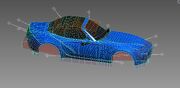
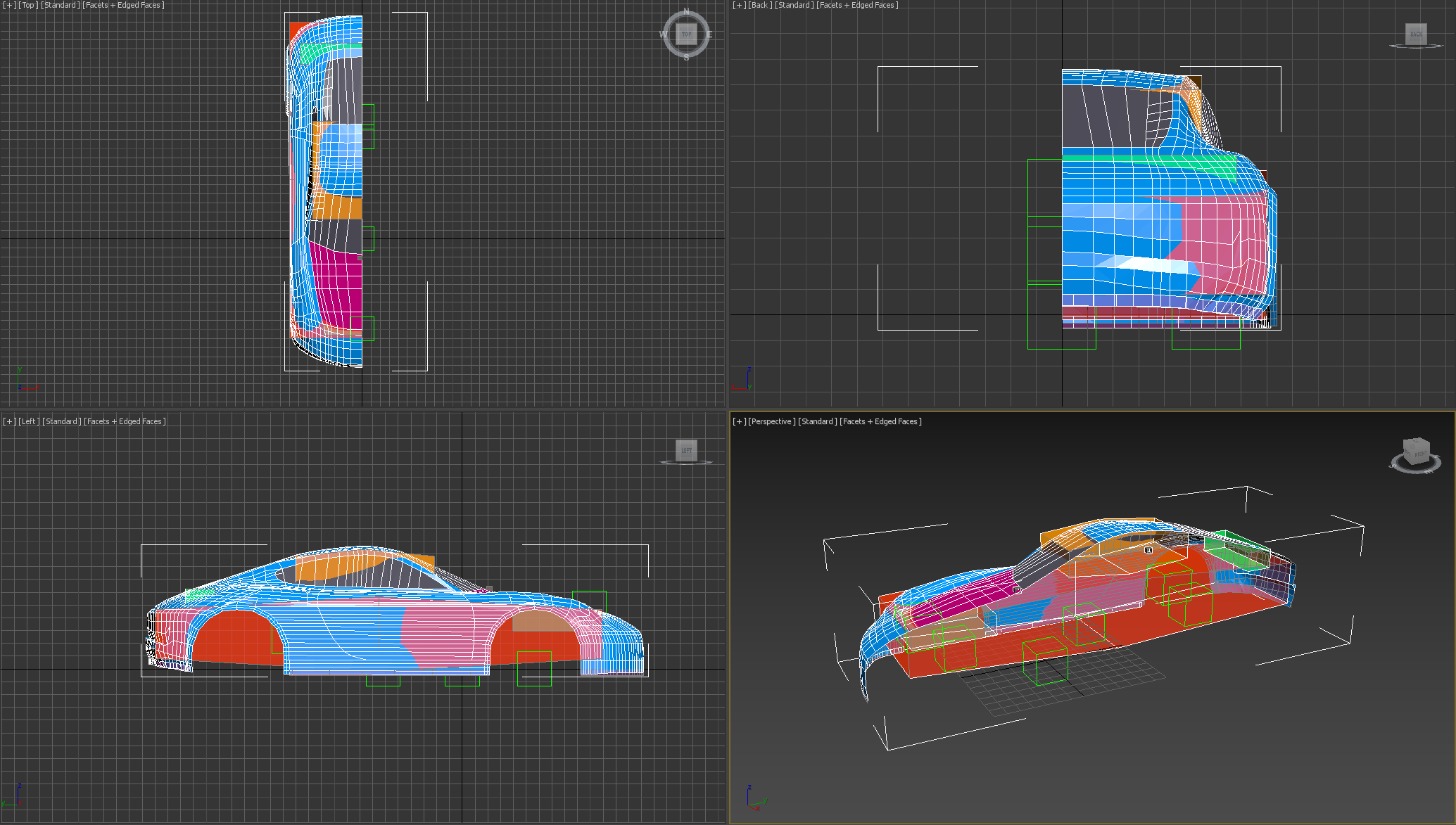
Automation uses various mesh objects to help calculate various aspects of the car, or to help the fixture system work correctly.
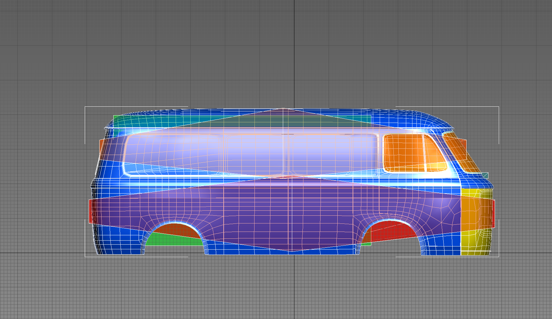
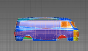
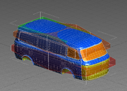
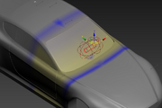
1: Cabin Bounds box. Used to determine cabin volume and interior weight. Must be tallest in the middle, tapering to each end. Only measured by it's bounding box, not it's total volume.
2: Lower Bounds box. As per cabin, but for the overall lower body of the car. Has a lot of impact on weight.
3: Cargo Box: determines cargo volume. Put it in the boot/rear hatch area, roughly filling where cargo would go.
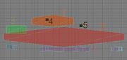
|4: Driver Head Position: Currently not used, but may be required for future features. Put where the drivers head goes.
5: Bonnet Cam Postiion: but may be required for future features. Put where a bonnet camera would go.
6: Lip Placement strip: Used for placing lips/sideskirts/exhausts. Just a flat strip of polygons running around the lower edge of the car body.
7: Front Bounds: (Not Shown) Determines the cargo space at the front of the car for rear engine vehicles.
These boxes should be part of the same mesh as the car.
Notes for Cabin and Lower bounds boxes:
All body boxes are measured by the volume of the bounding box, not the volume of the mesh itself. The reason they are tapered is so that, for example, changing the height of the back of the roofline doesn't make a huge difference to the cabin volume (as it would if the box was box shaped)
Also note that you'll need to make the boxes of a size that accurately represents the volume of the car, note in the above picture that the orange cabin bounds box stops well before the front of the windscreen, this is because the windscreen has a steep slope on it, and if the box went all the way to the front of the car it would make for a much larger amount of cabin space than is realistically available. The same can be seen with the body box stopping before the front of the (very tapered) nose, and the cargo box that doesn't go all the way to the back of the sloped boot.
So always think about the bounding box of these boxes, and if it accurately represents the overall volume correctly.
Applying materials
For 3DS-Max: create a new multi-subobject material, and assign materials to it as needed. The names of those materials don't matter.
For Maya or Blender, assign faces of the mesh to different materials. The names of those materials don't matter.
Car Body Material Options
Automation uses a set of placeholder materials applied to the mesh to define different paintable parts of the car. Only one of each material is supported. If you need more materials to assign, consider adjusting your mesh, because there are no more materials to assign than those listed here and you can only have one of each 😉.
On import to UE4 these will be replaced with the correct materials and inform the game what various areas of the car are used for and what materials they require.
The following materials are used on cars:
Bonnet: Defines where you can set bonnet colour.
Bumper_Front: Defines where you can set front bumper colour.
Bumper_Rear: Defines where you can set rear bumper colour.
Chrome: Used to force an object to be Chrome.
Paint: Primary Paint colour. Every panel other than the bonnet and bumpers will likely use this. Defines where you can set main car paint colour.
Paint_Two_Tone: For areas that should use the secondary paint colour. Will default to primary paint colour otherwise.
Plastic: Used to force an object to be Plastic.
Reflective_Mirror: No longer used, but kept for legacy compatability.
Soft_Top: for Soft Top convertible roof, or any other cloth parts.
Trim: For objects that change with Trim material in game.
Window_Pillar: For objects that change with the window pillar material in game (distinct from the window trim).
Window_Trim: For objects that change with Window Trim material in game.
Windows: Opaque window glass.
Wing_Mirror_Trim: No longer used, but kept for legacy compatability.
BonnetCam: Defines where a bonnet camera would go. defines where the bonnet camera is for exported cars.
CabinBounds: Defines the size of the cabin.
CargoBounds: Defines the size of the cargo area.
DriverCam: Defines where a driver camera would go. defines where the driver camera is for exported cars.
FrontBounds: Defines the size of the front cargo area on rear engine bodies.
LipPlacement: Invisible material for the skirt around the bottom of the car, used for stamping lips and exhausts.
LowerBounds: Defines the size/volume of the main body of the car below the window line.
creating your body morphs
Automation car body mods support both Morph Targets (Shape Keys), and Skins for morphing your design. You can mix and match as many of each as you want.
creating morphs using a skin
Skinning is the system used to allow the player to drag around and deform the car body in Automation. It's done via weighting specific vertices to various "Bones" that are a representation of what the player is dragging in game when deforming the body.
It is also probably the single most confusing step of car creation in Automation, as it done in a way that doesn't have a great deal in common with any other widely used game art process.
It uses the same tools (the Skin modifier) as skinning a character in a 3d modelling application, so referring to some tutorials around character skinning may give you useful insights into the toolset, but the way we use it is quite unique.
Basic Skinning Theory
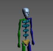
Spoopy skeleton. This is how you'd expect bones to look in a character
Bones: A bone is usually an object in the skeleton of a character used to define the animation of that character. Rather than manually moving every vertex of a character to animate it, you just move and rotate the appropriate bone, and the skin will determine which vertices need to move. Bones are usually attached to each other in a hierarchy, so that if you rotate a leg bone, the foot bone will move with it, and the toe bones will follow the foot etc.
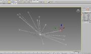
In Automation the bones are still used to define which part of the skin moves, but are mostly non-hierarchical, just floating in space around the car without any connection to each other.
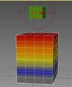
Skin weight colours. The top row of verts is skinned to a value of 1, (Red) descending towards 0 (grey) as you go lower down the model
Vertex Weights: Every vertex on a skinned model has a skin weight to each and every bone. This will be a decimal number from 0 - 1 defining how much that vertex follows the movement of a specific bone.
A vertex weighted 1 to a bone will exactly follow that bone's movement, a weight of .5 will move half as far as the bone, and a weight of 0 won't follow the bone at all. Bodies in Automation support up to four bone weights per vertex. Weights of 0 should be deleted.
The way we use Skinning (with "Normalise" set to on) only allows a bone to have a total weight of 1 between all the bones it's skinned to. For example a vertex could have a weight of .5 to bone1 and .5 to bone2. But if you set it to .6 on bone1, then bone2 would have to drop to .4 to maintain a total weight of one. Weights of more than 1 will cause errors in-game.
When you morph the car in-game, your mouse movements move the bone, and the vertices follow the bone.
Setting up bones for car skinning
You can use basically any object you like as a bone in 3DS-Max, but the preferable method is to use Dummy Objects. As it won't get in the way of viewing the car, shows links to confirm it's correctly bound to the root bone, and can't be accidentally made visible in game.
In Blender, create an armature object and add bones in the Edit Mode of the armature.
Bones should float freely around the area which they will deform. All bones should be parented to another bone at the origin of the car called "Bone Root". The naming and hierarchy of this bone is important. if your root bone is not called 'Bone Root', things will not work.
Note: It is ESSENTIAL that the bone root is named "Bone Root", otherwise the body will not work correctly!
The other bones you create are up to you, and vary depending on the shape of the car and which parts can be deformed attractively, but almost every car will have bones for:
Wheelarch flares
Windscreen rake/top angle
Rear window angle
Boot/rear length or angle
etc...
There is no real limit to how many bones you can have, but each vertex can only be skinned to 4 different bones, and it can be very difficult in-game to select and deform an area that's skinned to more than 2 bones. This is because in-game, when you hover over the car, the bone weighted the most to the vertex under your cursor is the bone that you will be affecting.
Bones should be created floating near the part of the car they deform. Their location isn't important to how they function ingame, but having them placed correctly makes it much easier to understand what each bone is for adjusting their limits in later stages of the modding process.
Note that if you are using the 3DS-Max script, you do not need to create bones for anything on the opposite side of the car (e.g wheel arches on the other side) as they will automatically be mirrored when you mirror the car body. If you are not using the script, or you are using Maya or Blender, all bones that should mirror their actions on the other side of the car (such as wheel arches) should have the correct naming nomenclature so they work correctly in-game. The following suffixes work for mirrored bones in Automation:
_opposite
_R
_L
Applying Skin and Adding Bones
For 3DS-Max
1: Add a "Skin" modifier to the modifier stack of your car body mesh
2: From the Parameters section of the Skin Modifier, Press "Add Bones"
3: Select all the bones from the list, and press Select to add them to the skin. (You can use the filters to make sure you're only getting helper objects like dummies in the list)
For Blender
1: add an armature modifier
2: select your armature
Weighting the skin
Now comes the complex bit. Weighting skins is a difficult and creative proccess that's almost like remodeling the car into different shapes, but with only skin weights to do it with.
Wheelarches are often the easiest place to start on a new model and a good way to start is to move a bone a reasonably large distance in the direction you want it to move (say 30 - 50cm) and then start weighting to that bone's new position.
For 3DS-Max
moving the bones
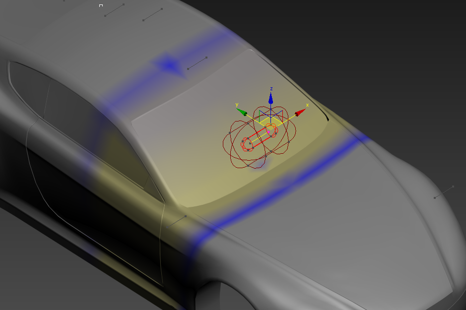
Select the bone or dummy object and move it
Editing the weights
Go back to the car mesh and press "Edit envelopes" and tick "Vertices" under the parameters section of the skin modifier, to get into the correct mode to edit vert weights.
While you're in "Edit Envelopes" mode, click on the little grey stick inside the bone you wish to edit weights for
Make sure the "Rigid" box is unticked, and the "Normalize" box is ticked.
Select some vertices, and by clicking and dragging upwards on the arrows next to "Abs Effect" set some weighting to the bone.
As you set the weight higher, the selected vertices will move closer to the position you've moved the bone to.
If you need finer adjustment of the weighting, hold Alt while you're dragging.
Remember the higher you set the weight, the faster that bit of car will move with mouse input, and the less weighting will be available to assign to other bones. This isn't too important on wheel arches, but can be on other parts of the car which share more bones.
Note: If your "Abs Effect" values are jumping to 1.0 when you modify them: enter "Edit Envelopes" mode, select the bone root, select all vertices, and then assign the "Abs Effect" to 1.0. This will correct the issue. This happens because all weights on a vertex need to add up to 1, and if the current bone is the only bone assigned to that vertex, then that bone cannot have a weight less than 1. by adding the bone root as a second bone, you can now adjust the weight of the bone you want and the bone root will take the remaining weight.
For Blender
moving the bones
Select the Armature object and either press ctrl-tab to go in to Pose Mode, or select Pose Mode from the modes menu:
Editing the weights
Bones in Blender affect vertex groups of their same name. To skin a mesh, you assign vertices of that mesh to the vertex group (of the same name as the bone you want them to be affected by), and then adjust the weight of that vertex (as a 0-1 value) to that vertex group.
Create a Vertex Group from the Object Data tab with the same name as each bone.
Select vertices you want to be affected by certain bones, and assign them to the matching vertex groups.
in the 'item' panel (accessed in the Viewport by pressing 'N'), adjust the weights for the vertices.
Effectively what you're doing here is using the weighting to remodel the car into the shape you want it to be at the furthest extremes of bone movement. If you can make it the correct shape with the bone moved to its maximum position and with the bone back in it's normal position, everything in between should take care of itself, and any bone position in between should look good too.
Windscreens are also a good place to learn to skin, as you can basically move the windscreen bone forwards, and then try your best to use skin weights to make an almost vertical windscreen. If you can get that working correctly, then you should have a bone that lets you smoothly change the angle of the windscreen
Creating Morphs using Morph Targets or Shape Keys
For Automation, we support using morph targets and shape keys for morphing a car body. This is done by storing a default value (the base car) and a morph to morph to (the morph target/shape key), and interpolating between those two shapes for every morph. We support morph values between 0 and 1 only, and only in one dimension. This is why skinning is better for the corners of a car body, because a skin allows for a full two dimensions of movement for every morph. It is up to you to decide which method you would prefer to use. Morphs are certainly easier.
In Blender
Create a new shape key.
Select the shape key
You can now edit the mesh to be in the new position you want it to be in for that morph.
Repeat for as many morphs as you would like, taking in to consideration that for every vertex that each morph affects, that will add to the total polygon count for that body. If you have too many morphs on too high a polycount body, you will have a very laggy car body!
In 3DS-Max
I do not recommend this, but you can do it if you really want to.
duplicate your mesh. Adjust your mesh, without adding or removing any polygons, to create your morph target.
create a 'morpher' modifier, and put it above the 'edit poly' modifier, and below the 'skin' modifier (if using)
pink the duplicate mesh as one of the morphs
repeat for all morphs yes its that tedious i hate 3ds-max
Morph Creation Tips
Look carefully for any strange deformations in panels when moving your bones, it's very important that panels remain as smooth as possible when deforming, as reflections will very obviously show any kinks. The above example of the windscreen is a great example of a morph that deforms the overall shape of the body too much (look at the top of the windshield, how it becomes a curve and then eventually a kink. This is bad). If I had the time, I'd go back and fix that one 😉
Test out what happens if you move two nearby bones at the same time, sometimes two bones' movement combined can cause strange polygon overlaps, though this can often be avoided with careful skinning and a smooth falloff of weights between the two bones.
Don't try and make too many different skinned areas, 10 - 12 is a sensible maximum, and try and avoid more than one bone effecting the exact same area (some overlap is okay though), as this can make them hard to select in-game.
Sometimes you'll have to make mesh changes to make your car deform nicely in an area. Mesh/edge flow is very important to getting good deformation.
Don't forget that any weighting you give a vertex to a bone will be taken from another bone to keep a total weight of 1. This can get very confusing and cause you to chase your own tail a bit. You have been warned! This isn't so much an issue in Blender but in 3DS-Max Ohhhh Boy I almost tore my hair out on more than one occasion.
UV Unwrap
If you're planning to do a pelt unwrap as described here, please swap this unwrap step with the mirroring step, and perform your mesh mirroring first. If you plan to use the 3DS-Max script for unwrapping, please perform this step first and then move on to mirroring.
Fixture unwrap Fundamentals
UV unwrapping is the process of unfolding the mesh onto a flat 2d plane that describes which pixel of a texture is applied to which bit of the mesh.
Think of it like taking a completed papercraft model of a car and unfolding it back to a flat sheet.
In most games, UV mapping is important for how the actual visible textures on objects , but in Automation, it's mostly important for how the fixture system works. When you stamp a fixture (such as a headlight, grille, door handle onto the car), it projects a hole into the alpha (transparency) channel texture in the shape of the fixture.
For the holes to be projected correctly, you must Unwrap the car as one complete piece without cutting any polygons apart, moving anything around too much etc, otherwise the holes would project across multiple parts of the car and give you holes in unwanted places.
The UV unwrap must also give a fairly even amount of texture space to each area of the car, as any low resolution areas will cause jagged holes around the outside of fixtures when stamped on.
It is for all of these reasons that the unwrap of a car mod has to be what's called a 'pelt unwrap'. Imagine you have a bear kill, and you want the bear hide to be a rug on your floor, but you don't want it to be in a million pieces, so you cut it only where you need to and stretch the rest out. This is the concept behind a pelt unwrap. For Automation cars, it looks like this:
Unwrapping a car with a pelt unwrap
Make sure your car is one element
This part is important as it defines how the pelt unwrap works, which is itself important as that's how the fixture system knows how to cut holes in the car. If parts of the car are not connected in both the 3D viewport and the UV viewport, the fixture will cut an incorrect hole. This only applies to the car itself, not to the bounds boxes. The bounds boxes do not need to be correctly unwrapped, as they are invisible and do not contribute to the fixture stamping.
In 3DS-Max, enter the Edit Poly modifier and click 'Element' mode. Select one face of the car, and hide unselected faces.
In Blender, select one face of the car and press 'CTRL-L' to select linked faces, and 'SHIFT-H' to hide unselected faces.
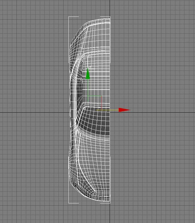
If your selection ends up looking like this, your car is not one element, and has unjoined faces between the selection and the rest of the mesh. This will not work. Join your mesh together properly.
If your selection looks like this, with the entirety of the mesh selected, then you have done it correctly and there are no un-joined elements. good job!
Doing the pelt unwrap
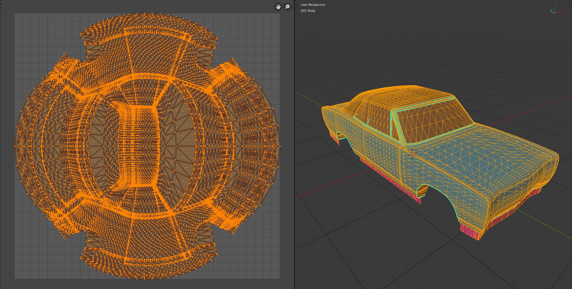
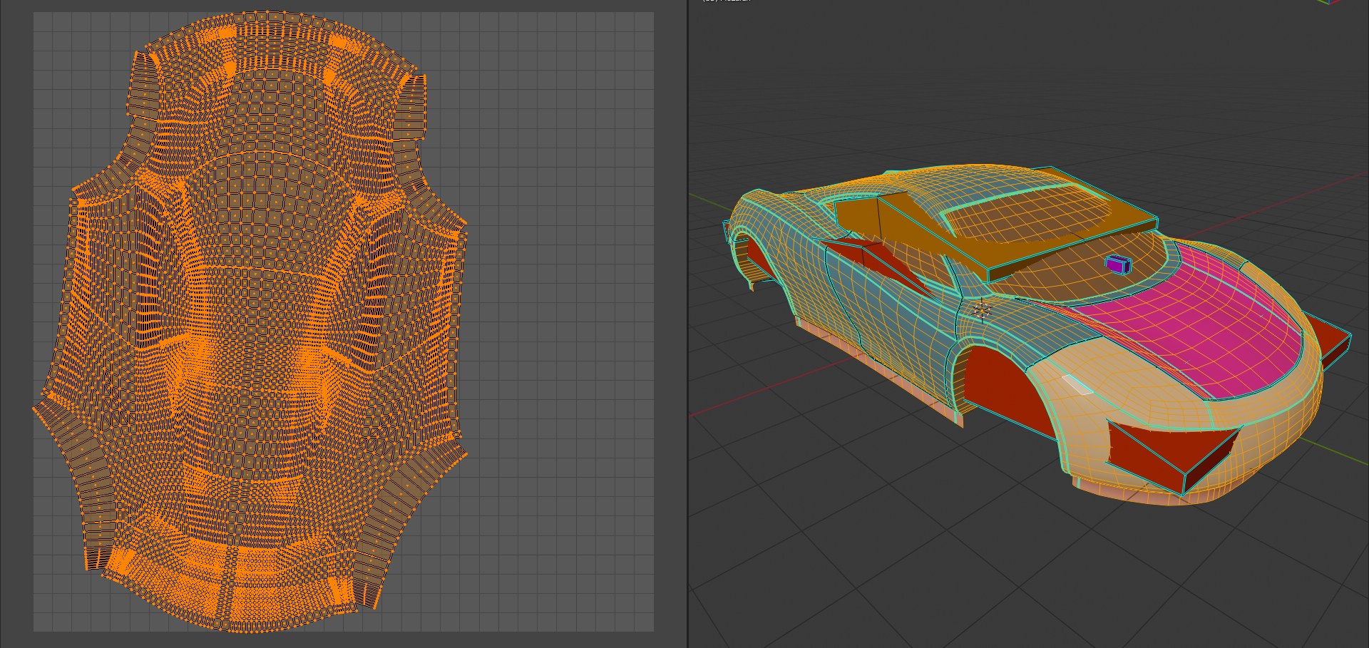
However it's done in your choice of 3D application, perform a pelt unwrap on your car. In Blender, it looks like this:
Next we need to orient the unwrap so that the centre of the car in the UV sits on the centre-line of the Y axis, and scale the unwrap up so that it covers as much of the UV space as possible:
It is vital that the top and bottom halves of the unwrap here are perfectly symmetrical, and that the centre line of the car is perfectly straight along the middle
Make sure this unwrap exists on both the first and second UV channels. The first channel will be used to calculate the normals, and the second channel will be used to calculate the fixture cutouts.
Unwrapping a car with the 3DS-Max unwrap script
Step 1: From the "Car Body Export Helper" utility (located on the utilities tab, with the hammer icon, in the top right of 3ds max), press the "Unwrap Car Body" button
Note: If you don't see this menu, go to utilities, then click on "MAXScript", which will bring up the "Car Body Export Helper" option, then click on the name.
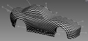
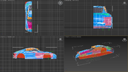
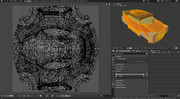
The UV unwrap should now be complete, and with the UVTESTING map applied, the result should look something like this
Note for finished bodies made via the script for 3ds-max
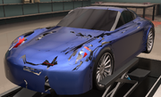
If you've finished your body and have it running in game but whenever you add fixtures it looks like this:
You need to follow these steps to fix the UV Maps:
Start off with your un-mirrored, but complete body.
Step 1
Apply the UV Test material and unwrap your body (which at this point is only half) with the "Car Body Export Helper Tool".
Step 3
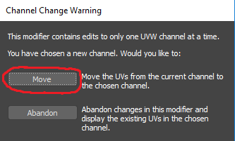
Add the "Unwrap UVW" modifier. Under the "Channel" panel, navigate to the "Map Channel" box and change the "1" to "2".
There should be a pop up, click "Move".
Step 4
Now move your "Unwrap UVW" modifier so that it sits below the "Skin" modifier.
Step 5
Select your car object and mirror it using the "Car Body Export Helper Tool". After mirroring you will notice that your "Unwrap UVW" modifier has disappeared.
In conclusion: unwrap the body and apply the "Unwrap UVW" modifier. Change the "Map Channel" to "2" and then click "Move". After which you will move the "Unwrap UVW" modifier below the "Skin" modifier.
You can now follow the export steps to re-export!
Mirror Half Body
The traditional method
Mirror your mesh
If you've already unwrapped your mesh, select the mirrored half, and flip the UV of that half along the Y axis:
a mirrored mesh before mirroring the unwrap
a mirrored mesh after mirroring the unwrap
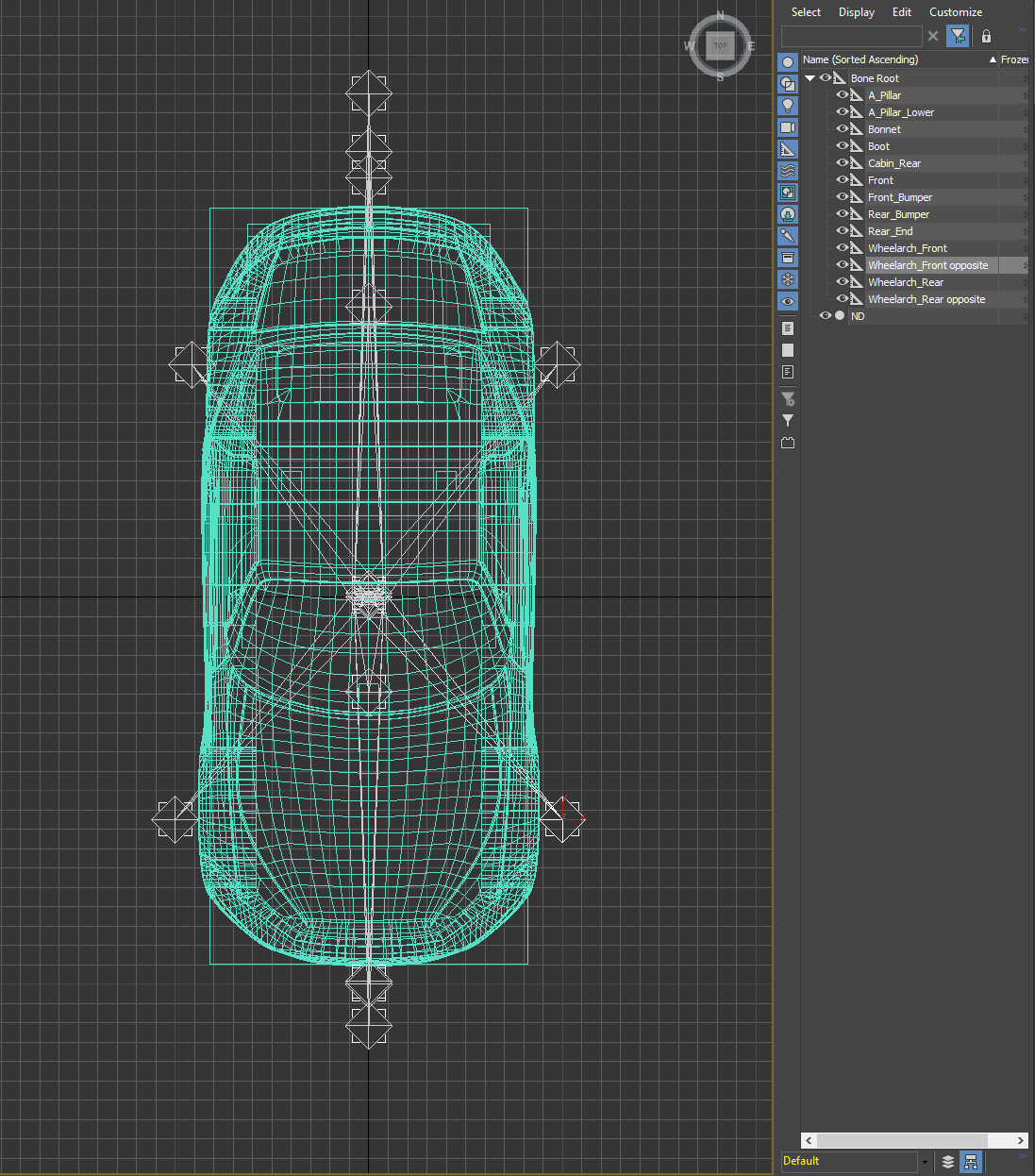
Duplicate the bones for the wheel flares on the opposite side, matching the distance from the centreline. Set the name of the mirrored half to the same as the un-mirrored half with '_opposite' at the end of the name of the bone. Duplicate the bone weighting from the non-mirrored half, rename it to match the mirrored bone, and clear the weighting for each on the opposing side so that the weighting for each wheel flare only includes the respective wheel:
If you're using the optional 3DS-Max script
Mirroring is simple, from the car body export tools utility, just press "Mirror Car Body". This will mirror the mesh, mirror the UV unwrap, and duplicate the required bones.
Fix all the things you just broke mirroring the car body
If you're using the 3DS-Max script
Check wheel arch bones have their opposite counterparts created
Wheel arch bones require an opposite bone. This is to allow the game to morph the wheel arch on the other side of the body in an equal but opposite direction to that which you have moved. (The same can apply to any other bone that moves along the X-axis. e.g. a running board morph).
When the mirror script is run, it determines which bones require an opposite by checking all the vertices on the zero X axis for each bone. If none of these vertices have a weight value then the script will create an opposite bone.
If, after running the script, your double sided body does not have the expected opposite bones, then you will need to go back to your original half body and check that none of the vertices for that bone on the Zero X Axis has any weight applied to it. Remember that zero weighted bones still count as having a value and you should use the "remove Zero Weights" button to remove these.
One method to check for weights on the zero X axis is as follows.
Ensure that all vertices of your mesh are visible
Select all the vertices along the zero x-axis
Open the weight table (found in the weight properties rollout).
Set the weight table view to selected vertices.
Scroll down the list of weight for the bones in question, any weighted verts should be easy to spot as there should not be any. these can be zeroed by right clicking the weight value. (You may want to make note of any weight values for other bones (exc. bone root) on that vertex, as these may alter as a result of the above and you will want to correct them.
Once all erroneous weights have been zeroed, use the remove zero weights button.
These steps should ensure your opposite bone is created when the mirror script is run again.
Ensure other bones do not have opposite bones when not required
In some cases your body may have bones that are purposely designed to morph vertices on the outside of the body that are not intended to move along the X axis. E.g. The "Hofmeister Kink" found on the 10sSedan02 series of bodies. The mirror script may create an unwanted opposite bone for these.
This can be avoided by temporarily weighting a vertex on the zero X axis to the bone in question. Ideally pick a vertex that is weighted only to the root bone so as not disturb the weights of other bones. Once the mirror script has been run you can remove the temporary weight applied to that vertex.
Check both halves of the body are welded together
The mirror body script should weld both halves of your body together, however for "reasons" (3DS-Max is Spaghetti) this does not always occur. This can be seen by your body having an unexpected crease or seam down the centre.
Once you have welded the two halves together, perform a visual check to ensure that no unintentional welds have taken place. e.g. top and bottom vertices on a window frames. If this happens, undo your weld command and select the centreline vertices in smaller chunks and avoid selecting the verticies in question at the same time.
Check skin for distortion along the centreline vertices
When two skinned vertices are welded together, either automatically via the script or manually, 3dsmax will attempt to combine the weights of both the old vertices into one. Unfortunately it's not very good at it and many of the welded vertices on the centreline end up with odd weights. This results in a distorted skin (see below). This isn't an issue when using Blender.
To correct the distortion you will need to check and correct the centreline vertices. The most methodical way is to start from one end of the body and work your way to the other end as follows:
Expand the skin modifier and select Envelope.
Open the weight table and set to selected vertices.
Select the central 3 vertices at one end of the body and view the weight values in the table.
Where the mesh is distorted you will usually see one vertex in the weight table that's the odd one out.
Amend the values of this vertex to match those either side of it. (For vertices with more than 2 bones you may need to untick normalize to stop max from altering your amendments - remember to re-enable it once completed).
Repeat the above steps working along the body till you reach the other end of the body.
Check the same UVW mapping exist on the first two UV channels
In 3DS-Max
To Check the maps:
Under the utilities tab click on the more... button
Select "Channel Info" from the list and click OK
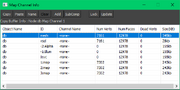
Click the newly appeared Channel Info Button and review the map channel info
The bottom 3 lines of the above screenshot represent the 3 uvw maps. In this case the maps are identical, as they should be. If however there is a mis-match between the three maps (this can be either nill data or just different numbers of verts) then they will need to be be corrected. If your body does not have 3 maps then see here.
In most cases Map:1 is the correct one. One method of correcting the maps is as follows:
in the channel info box select the line representing the correct map
select copy
select one of the incorrect lines
select paste
repeat for the other map if also incorrect
close the channel info box and click on the modifier stack tab
move the "UVW Mapping paste" modifier(s) to between the skin and the mesh
collapse the modifiers into the mesh
In Blender
Open the object data menu and select the UV Maps menu. Open a UV editor and check that the UVs looks correct in the first two UV channels:
If one of these is not correct, delete it and duplicate the correct one.
Export Car Body to .FBX file
In 3DS-Max
This step is easy!
1: Select the car body, then go to File > Export > Export Selected
2: Save the FBX file somewhere. It won't actually be distributed with the mod when complete, but name it well, and put it somewhere in a properly named folder, where it'll never need to be moved or renamed (if you move it, UE4 will get confused if you try and reimport, which you will need to do if everything is not perfect, and nothing is ever perfect)
3: Make sure your export settings look like this image.
note: Occasionally you may get warnings on exporting the .FBX that the matrials are not compatible with the chosen format and objects may appear grey. This warning can be ignored, as we use our own materials.
In Blender
Select the armature and the mesh, then go file > export > FBX
Save the FBX file somewhere. It won't actually be distributed with the mod when complete, but name it well, and put it somewhere in a properly named folder, where it'll never need to be moved or renamed (if you move it, UE4 will get confused if you try and reimport, which you will need to do if everything is not perfect, and nothing is ever perfect) Make sure your export settings match like so:
Under main, make sure the forward direction is set to -Y forward, with Z up, Selected objects is set to True.
In Geometry, set smoothing to Normals only, and Tangent Space to True.
In Armatures, set Add Leaf Bones to False.
The animation tab doesnt matter as we do not use animations.
You are now ready to import your body to unreal engine
Import car body to Unreal Engine
Now it's time to bring all your hard work into Unreal Engine.
Follow the Modding page for installing and opening the Automation Modding SDK
If you've never used Unreal Engine before, now is a great time to watch this introduction to UE4 playlist from Epic. It's for a fairly old version, but most of it still applies.
Creating your Car Body Mod
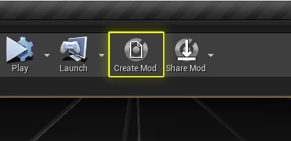
Press the "Create Mod" button in the top bar of UE4 Editor
Select the 'Blank Project', and fill out the wizard with all of your details, such as your name, and a short description of the mod you're making, then click 'Create Mod' to generate your plugin files.
The content browser window should now show your plugin content. This is where you will put all of your mod files. never modify any files outside of your plugin file. you can copy materials etc from the main content folder, but only if those files are copied to your mod folder. the end result of your mod should be a default content folder that is identical to the default state of the SDK, and all of your own modified files are within the one plugin folder you want to release.
You should now have an empty content folder:
Importing your car body to the mod folder
Press the 'import' button in the content browser with your mod content folder selected to import your car body .FBX file
In the following pop-up import options, make sure the following settings are exactly as described:
Skeletal Mesh should be set to True
Import Mesh should be set to True
Skeleton should be set to None
Import Meshes in Bone Hierarchy should be set to False
Import Morph Targets should be set to True
Normal Import Method should be set to Import Normals and Tangents
Material Search Location should be set to All Assets
Material Import Method should be set to Do Not Create Material
once you have configured the import dialog correctly, press 'Import', or if you are importing multiple car bodies, press 'Import All'.
You should now have a Skeletal Mesh (Pink Icon) a Physics Asset (Yellow/Brownish Icon) and a Skeleton (Light Blue Icon) in your mod content folder:
Check the materials are correctly applied
The materials applied to the car body denote what part of the car that is. They aren't so much placeholder materials as they are identifying materials. the materials that are applied to the car denote the category of paint on that material slot in-game.
Double click on the Skeletal Mesh for your car, you should then see a screen like this:
If instead, when you import a car, you see something more like this, Then you will have to apply your materials manually:
The materials to apply to the correct slots on your car body are located in Content/Cars/Meshes/Bodies.
This is the file that will contain all the stats about your car; how many seats it can hold, how many doors it has, what the wheelbase is, etc..
Create a Body Variant Preview Object in your mod folder from the Add New menu
Name your Body Variant Data correctly. The name of this file will determine the name of the body in-game.
Open the body variant data file. in the top field, drag and drop, or using the arrow button, put your skeletal mesh file in to the skeletal mesh data field.
The data inside the body variant preview file determines the stats of your car design. The data is set within the file, but updates in real-time in the body edit scene, which you should open first. Opening the body edit scene and loading your car will help you visualise what all the data in this file means.
Loading a Car For Editing
open the ThumbnailGeneratorLevel_Car
On the Top Bar, select the drop-down menu next to the Play button, and select Simulate.This will start simulating the game (or in this case, start simulating the thumbnail generator level). It is important that everything you do in this level is done while you are simulating the game.
In the world outliner, search for the BodyEditSceneBluetility This bluetility will be the interface between the level, which will have your car loaded in it, and your Car Body Variant file.
In the Details panel of the BodyEditSceneBluetility, you will find buttons and options for loading your car body.The Load- and Unload Body menu options will do just that, load you body, but you have to specify the body you want to load first, which is done in the Variant Asset menu:
Select your Body Variant file from the content browser, and put it in the Variant Asset List by either dragging-and-dropping it in to the icon, or by pressing the arrow button next to the icon.
Press Load Body, making sure that you are Simulating
You should now see your car loaded in to the scene, and you can begin to edit the data within the Body Variant file and see it update in real-time in the scene. This is really helpful for setting chassis data etc:
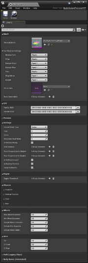
What all the Body Variant settings mean
Mesh
Skeletal Mesh is the physical mesh of your body
Car Material Settings are the default materials that should be applied to your body when a player loads it in-game
Mesh Data is a generated file that you dont need to worry about. We'll make one of these in the Generate Thumbnails stage
Bone Constraints is the physical limits of where bone morphs can be affected. This is an advanced menu for If you want to enter these manually. For most poeple, we have an easy system for assigning these bone limits in the Set Bone Limits stage. If a bone does not have limits, the player will be able to smoosh and move the bones around in any direction they want for as long as they want, and this almost never ends well. note: Morph targets don't need to have their limits set.
UID
Family GUID is an unique identifier that is shared between all variants of the same body family. If you are making more than one car body in the same family, they should all share this same family GUID
Variant GUID is an unique identifier that is unique for this body. Every body in Automation needs to have an unique GUID. If you, by chance, happen to generate or use the same Variant GUID as another body, when you try and select one the game may instead chose the other for you. If this happens, generate a new Variant GUID
Preview
You shouldn't have to set anything here, these will be populated in the Generate Thumbnails stage.
Settings
Variant Body Type determines the category of the body in-game. different categories have different bonuses and penalties
Year is the year that this body unlocks in Campaign. Bodies closer to the current year score better in some categories
Doors determine the number of doors on this body. The number of doors affects some demographic statistics
Maximum Seat Rows determines the maximum number of seat rows your body can have. This affects some demographic statistics
Is Release Ready is a dev button we use to allow us to configure and adjust bodies that are not ready to be in-game. if this button is un-ticked, you will not be able to see it in-game
Seat Options is a legacy option that is no longer used.
Front Suspension To Disable will disable those suspension options for this body. This is useful if your body is shaped such that certain suspension types clip through the body and you cannot solve it elsewhere
Rear Suspension To Disable will disable those suspension options for this body. This is useful if your body is shaped such that certain suspension types clip through the body and you cannot solve it elsewhere
Is Softtop Convert will set this body as a convertible with a soft top. This is for demographic calculations
Is Hardtop Convert will set this body as a convertible with a hard top. This is for demographic calculations
Cargo Subtracts will subtract the cargo volume from the cabin space. This is useful for making wagons etc where the more seat rows a body has, the less cargo space it has
Engine
Engine Placement is an array containing all the available engine positions for this body
Chassis
Footprint
Wheelbase is the wheelbase of the body in centimetres. Set this before setting anything else for best results
Track Width is supposedly track width in cm, but isn't actually measured accurately. Don't try and match it to real figures, just make sure the wheels sit correctly in the mesh (with correct tyres) and that there is enough room left in the wheel arches to make the tyres as wide as makes sense for the car (which might include having to use arch flare morphs). If you need room for wider tyres, set this a little narrower
YOffset is used to shuffle the mesh back and forwards to sit correctly in the middle of the chassis. If you're putting big numbers in here (say more than 15) you probably need to fix it on your mesh
Vertical Position
Default Suspension Height is used to set the default position of the ride height slider. Makes sure that supercars start off set low, SUVs set high etc
Height Offset moves the car model up and down as compared to the chassis/wheels etc. This should usually be set so that with appropriate sized tyres, and Default Suspension Height set to 0, that the wheels are nearly touching the top of the arches. Some cars might want to be set a bit higher (SUV's etc) but remember that when a car is set to ride height 0 it has very little suspension travel, so you should be setting height offset on the basis of the lowest the car could possibly ever sit
Front
Firewall Y is a 0-100 setting of how far forward the firewall is. Easiest to set in side view in Wireframe mode. Set to match your mesh's firewall. Important for engine bay size
Nose Length is used to set how far forward the engine bay goes. Important for engine bay size. Make sure the chassis doesn't stick out of the car, even when you've moved bones around on the nose
Cab Over is a tick box to say whether the engine is under the front seats of your body. Affects some statistics. Used for Vans etc
Rear
Rear Wall Y is the firewall position for rear/mid engine cars
Tail Length is how far the back of the chassis goes. Important for rear engine bay size, not very important for front engine cars, but careful it doesn't stick out of the car
Wheels
Max Wheel Diameter is the maximum Wheel & Tyre diameter in cm. Set this by adjusting the default tyre size to work out what the biggest practical tyre size would be, then putting that number in here
Min Wheel Diameter is the minimum Wheel & Tyre diameter in cm. Set this by adjusting the default tyre size to work out what the smallest practical tyre size would be, then putting that number in here
Default Wheel Diameter sets what tyre diameter is loaded on the car by default. Set it to something sane and average for the car type
Default Rim Diameter sets what rim diameter is loaded on the car by default. Set it to something sane and average for the car type. Remember to set correctly to keep a tyre profile that makes sense for the type and age of the car. Older cars MUST have high-ish profile tyres, due to ingame restrictions on using low profiles in early eras
Default Wheel Width sets what tyre width is loaded on the car by default. Set it to something sane and average for the car type
This is a legacy option for older bodies, you should not need to touch anything in here unless you are converting a pre-UE4.24 mod.
Body Boxes
This contains all the sizes and positions of the body boxes, and are generated automatically in the Generate Thumbnails stage
Set Bone Limits
Once you've set all the other car body settings, you'll need to set the limits for the bone movement.
While simulating in the car body scene,make sure your car is loaded, and select it
You should now see a set of blue squares in the location of your bones when you set them in your modelling program. Click on one of these blue squares, and start to move it along an axis to see how it affects the body. You can set the current position of the bone as the new limit of that bone by right clicking on it and selecting 'add to limits'
Right click on a bone and select "Move All bones to Bind Pose" to move the bones back to their default location
Note that if you accidently set a bone's limits too far, the only way to fix it is to right click, "Reset Limits" and then set the limit again.
Note the following other options on right clicking a bone
Move bones to Max: will move a bone as far as possible in the + axes it can move
Move bones to Min: will move a bone as far as possible in the - axes it can move
Reset limits: Will remove all limits set on this bone
Move all bones to bind pose: Will move bones back to default position
Also note: bones that appear red are bones that exist in the skeleton but are not applied to any vertices on the car
Generate Thumbnails
While simulating, load your car body.
In the Body Edit Scene Bluetility, click 'Generate Thumbnail'
You should now have two more files in your mod content folder, but don't let their lack of a 'need to be saved' icon fool you: these files do indeed need to be saved. Right click the files and save them. If you do not save them, they will stop existing.
You are now done creating all the files and settings you need! you can now export your mod body.
For additional variants, repeat the same process for each CPP. If you copied the CPP from one variant and edited it for a new one, this will replace the original thumbnail. To avoid this problem, clear any thumbnail from "Variant Preview Texture" on each additional variant before generating their thumbnails.
Exporting Your Car Body
In Unreal Editor, at the top toolbar, select "Share Mod" and then click on the name of your car body.
Select a path where there are no spaces in the file path.
Example:
"C:\Users\Name\Documents\Unreal Projects\AutomationGame" is NOT OKAY, can you see why? There is a space between "Unreal" and Projects".
"C:\Users\Name\Documents\ModExport" is OKAY because there is no spaces in the file path.
Once your build is successful, you need to launch the "Automation - The Car Company Tycoon Game Workshop Tool" from your "Tools" which can be accessed by hovering over "Library" in Steam.
Enjoy your new car body!
FAQ
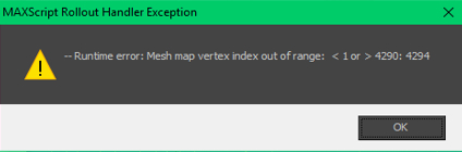
Q: I get a Max Script error running the script to unwrap my body like so
A: Car bodies in UE use 3 UVW maps and your mesh currently has less. To ensure you have enough maps take the following steps
Q: I get a Max Script error running the script to mirror my body like so
A: Save the body file as is, close 3dsMax and then reopen the file. This fixes most instances of this error.
Q: Unreal won't open the SDK project files
A: Make sure you're running the correct version of Unreal Editor. It should be version 4.21.2 (4.24.4 If your making it for the open beta)
Q: I got my body in the game, but it looks weird whenever I apply fixtures
A: Refer back to Step 6: UV Unwrap where it addresses this problem.


