Fast Rundown
- Rims are Child Blueprint Classes of the base class 'Rim'
- Rims are composed of a single Morph-targeted Skeletal Mesh with two morph targets
- Rims can have one or two materials
- Need a Preview Thumbnail to show up at all in-game
How Morph Targets work
A Morph Targeted mesh is a mesh with certain baked states for the position of each of its vertices.
Essentially, a Morph-Targeted mesh has a base mesh (the default state of that mesh), and a separate mesh for each state that the mesh can be in.
This means that the base mesh and each of the morph targets must have the same vertices, faces, and edges.
So plan ahead, and be ready to re-do all your work again, and again, and again... when 3DS-Max decides to add vertices somewhere for no apparent reason, or you've run in to a situation when creating your morphs that requires a different mesh flow:
Make sure to always have the XView Statistics open in 3DS-Max (or its equivelant in your modelling package) to ensure you haven't managed to create additional verticies when making your morph targets.
If, upon completion of a morph target, your mesh does this:

If this happens, you've added/subtracted some verts from your morph targets.
...Then you've got a messed up vert structure and you're going to have to re-do all your morph targets again. If you can't even select a mesh to be a morph target, then you've added some vertices somewhere and will still have to re-do all your morph targets again.
Morph Targets, Smoothing Groups, the .FBX File Format, and the complications that lie therein
Smoothing Groups define groups of faces that share smooth edges. For edges that should be hard, the faces on either half of that edge should be in different smoothing groups. For more information, see the official 3DS-Max documentation on Smoothing Groups.
Smoothing Groups and Morph Targets
Unfortunately, Smoothing Groups don't work for Morph Targets.
Well, they do. But only within the authoring software. The issue is with the .FBX file format that we use as an intermediary format between 3DS-Max and UE4.
.FBX files don't actually have support in the file format itself for supporting smoothing groups for the morph targets. Smoothing Groups for the base mesh does work, but as you start to move towards the morph targets, the smoothing groups start to disappear, and you end up with a mesh with really mushy looking edges as everything becomes part of the same Smoothing Group.
How do we go about solving this gaping hole in .FBX files?
Physically break apart your Smoothing Groups!
- Mesh has a hard edge? Cut it.
- Faces should be part of a Smoothing Group? They're now in a separate element.
It's a pain, and sometimes 3DS-Max will forget to create the new vertices for the separated edges and you'll run in to the issue stated in the How Morph Targets Work step, but it's the best solution there is as of yet.
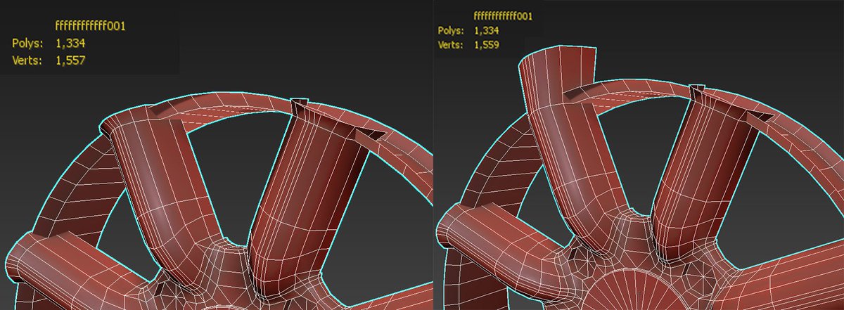
A good alternative to separating all your edges in to separate elements is to simply chamfer everything to have a slight curve to it. This also helps make the Rim look cleaner:
I've chamfered the edges of this Rim to avoid having to cut its smoothing groups in to different elements
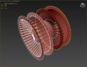
How Morph Targets are Used for Rims
We use morph targets for defining the radius of the rim, and the offset of the rim.
- The Base mesh is the lowest offset and smallest radius.
- The Rim Scale is the largest radius of the Rim.
- The Rim Offset is the farthest out the Rim gets.
What Morph Targets do I need?
For Rims, we have two Morph Targets, plus the base mesh to be morphed:
- Default Rim
- Rim Scale
- Rim Offset
A Rim starts off at its smallest scale and smallest offset. So the Scale morph-target will scale it out in the Y/Z axis, and the Offset morph-target will scale it out in to the -X axis
As an example, here's the base mesh for a rim:


Rim Base Mesh
its Scale Morph:


Rim Scale Morph
And its Offset Morph:


Rim Offset Morph
Creating the Morph-Targeted Skeletal Mesh
We'll be using 3DS-Max for this example, but any 3D Modelling package that supports Morph Targets will work as Rims do not require any custom scripts.
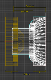
Rim Default Dimensions
Because of the translation between Kee engine and UE4 plus the translation between Metric and Imperial, Rims have strange and specific default dimensions. They are as follows:
- Outer radius: 13cm
- Inner radius (axle end): 5.88cm
- Outer Rim thickness: 5.7225cm
- Outer Rim inner edge distance from X-axis: 3.109cm
- Outer Rim outer edge distance from X-axis: 2.614cm
- Scale morph radius: 37cm
- Offset distance: -12.597cm
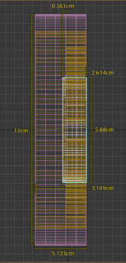
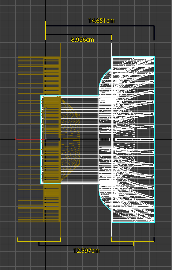
Note the below screenshot for a visual representation of these dimensions:

Orange: an existing Rim. Pink: Our currently created example rim with an outer radius of 13cm and a depth of 5.7225cm White/Blue: The inner radius of the Rim (5.88), where it will connect to the axle and brakes
Rim Orientation


Rims face towards the -X axis, with +Z being up
Rim Position
A Rim's centre point (the point at which it connects to the rest of the wheel/axle) is 0.561,0,0. (that's 0.561cm in the X-axis, and 0 in the Y/Z axes)
Please don't judge us too hard on these numbers - the uncertainty and finickiness of morph targets combined with a translation between metric and imperial units precludes any sanity
Creating the Base Mesh
Base Mesh format and scale
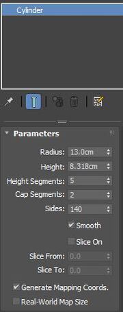
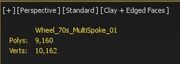
I have created a cylinder and set it to the default dimensions. I've also added a number of sides (I find that sides >100 give a good result. The more the merrier, but to make life easier I find it better to make the number of edges for the Rim be a multiple of the number of spokes for that Rim):


Close-up of the cylinder properties
Note that the yellow mesh has a small lip on its outside edge, making it appear to not be wide enough. Here is that rim from the front:

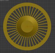
Creating the rest of the Base Mesh
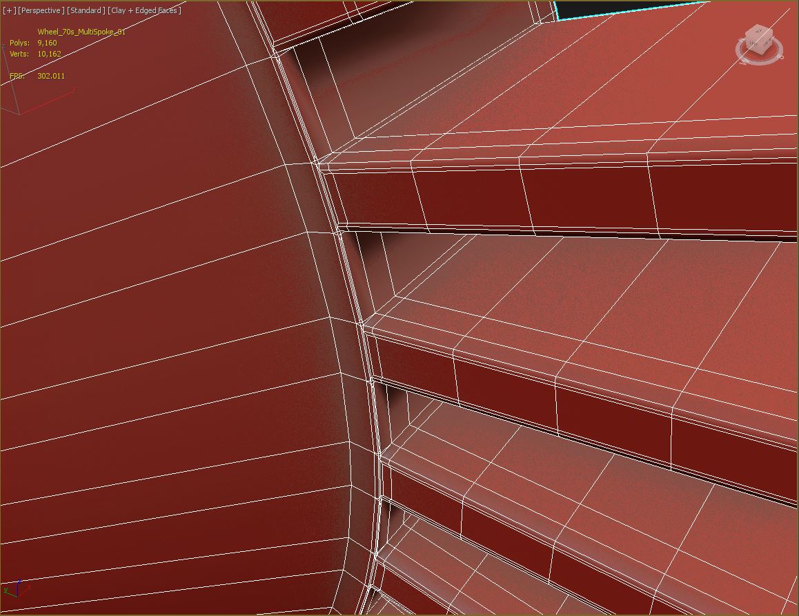
Go through the process of creating your Rim Base Mesh. A lot of this is going to be specific to the design you're going for, but keep in mind that this is the same mesh structure that you're going to need to scale out for the Scale Morph and the Offset Morph, so creating enough connecting edges is important. This Rim will scale out relatively simply, but I'm going to give it a subtle curve to its offset morph, so I've given it some extra edges along the spokes.


Not here that for this Rim I've created several edge loops along the spokes of the Rim to aid in the transition for these morphs.
Fixing Smoothing Group problems with .FBX and Morphers
So you've set up your mesh and assigned smoothing groups to it, but you remember that I mentioned earlier that Smoothing Groups don't work with Morph Targets. How do you go about fixing that? Consult This Section on Smoothing Groups and the .FBX File Format again for solutions to this.
Setting Material IDs
Rims support either one or two materials.
Create a multi-sub-object material with two standard materials in it, and apply it to your mesh.

then simply set your material IDs on your mesh to either 1 or 2.
UV Mapping your Base Mesh
The same process as with creating Fixture Mods works the same here. A Box UVW Map with a scale of 2,2,2 will do fine.
Creating The Morph Targets
It's important that you do not edit the actual mesh structure of your morph targets. If I have not made this clear enough, you will break everything if you add/subtract any geometry beyond this point.
Make sure you have your XView Statistics (or its equivalent for your authoring package) open and ready to check for anomalies.

If, at any point and for any reason when creating your Morph Targets, these numbers change: scrap what you're doing and re-start the Morph Target
Creating the Scale Morph Target
Duplicate your Base Mesh. This duplicate mesh will become your Scale morph target.
A Scale morph target extends out to a radius of 37cm.
For sanity's sake, I usually only scale out the outermost vertices of my mesh first, then scale out the interior of the Scale morph appropriately. For this Rim, the spokes should maintain their parallel-ness, but get slightly thicker for the Scale morph. If I were to simply scale these out with the scale tool, they would lose this property as the outside edges got thicker but the edges closer to the centre of the rim would not, so I will move these edges out manually.
The outside edges of your Scale morph should then look something like this:


Orange: Our new Scale morph White: Our existing Base Mesh


The same Scale morph compared to its Base Mesh
Other than the outside edges scaling out, and the edges connecting to the axle, you have full creative freedom in creating your Scale morph.
Creating the Offset Morph Target
As per the previous step, duplicate your Base Mesh. This duplicate mesh will become your Offset morph target.
An Offset morph will shift the outermost edges of your Rim (the parts of the Rim that lie on the 13cm radius that connect to the rest of the wheel) by -12.597cm in the X-axis.
The vertices that lie on the innermost radius (the ones at 0.561 on the X-axis that connect to the axle) should not move.
That means that the outermost edges of the Offset morph will be like so:
Here is an Offset morph compared to its Base Mesh:

These are some pretty nonsense numbers!
I find it helpful to keep an existing Rim in my scene and just snap my vertices to it for the offset instead of putting these numbers in manually. Unfortunately, unless you already have an existing Rim, this isn't helpful. But: it might be helpful to create a dummy mesh and set some of its vertices to these X-offset values to use as your snap vertices.
Other than the outside edges of the Offset morph, you have full creative freedom in creating your offset morph.
Assigning the Morph Targets to the Base Mesh
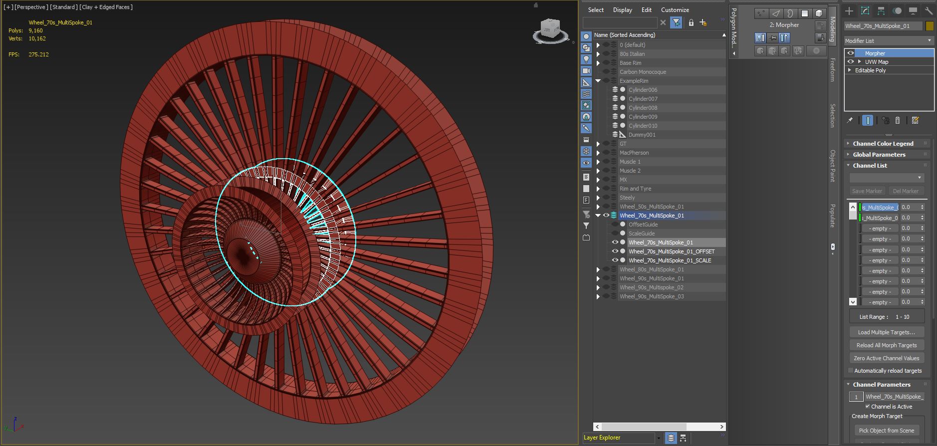

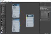
Create a Morpher modifier to your Base Mesh, and assign the Morphs in this order:
- Scale Morph
- Offset Morph
If you cannot select the morph targets, see here.
Mess about with the morph target settings to make sure your morph targets are set up correctly.
Export your Rim Mesh to .FBX
Select your Base Mesh with the Morpher modifier and two morph targets on it. Do not select the Scale morph or the Offset morph.

Select File > Export Selected, and export your Rim as .FBX

Make sure Smoothing Groups and Morphs are ticked for export, even though Smoothing Groups don't work for Morph Targets - UE4 still uses them for things.
Your Morph-Targeted mesh is now complete, and you can move on to setting it up in the Unreal Engine!
Rim Mod setup within Unreal Engine
Creating your Rim Mod plugin

Create a new blank mod.
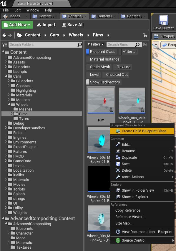
Navigate to Content/Cars/Wheels/Rims, and make a Child Blueprint of Rim, and move that child to your Rim Mod folder.

Importing your Rim mesh
Import your Rim.FBX file to your Mod Content folder. Make sure the .FBX is imported as a Skeletal Mesh, with 'Import Morph Targets' turned on.

The Rim mesh should be imported as a Skeletal Mesh, with 'Import Morph Targets' turned on.
Your Mod folder should now look something like this:
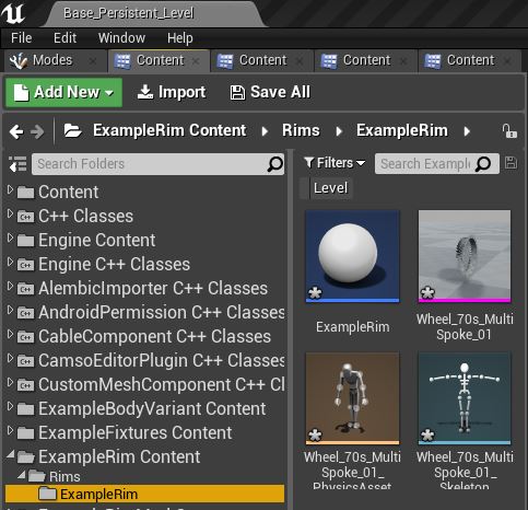

Setting up the Rim Blueprint
The Rim Blueprint and its Components
Rim Blueprints are relatively simple:


A blank Rim Blueprint with only the relevant settings exposed
- The Skeletal Mesh setting is where the rim mesh is set.
- The GUID is an unique identifier for the rim.
Assigning everything in the Rim Blueprint
Assign the Skeletal Mesh to the Blueprint and generate an unique GUID:

After doing so, you'll notice a 'Material' setting appear.
This is where you'll set the placeholder materials for your Rim.
There are
More Soon™
Saving and Compiling
Compile and Save your Rim blueprint and meshes:


Generating the Rim Thumbnail
Open the Thumbnail Generator Level, from Content > DeveloperSandBox > ThumbnailGeneratorLevel

Start simulating the level
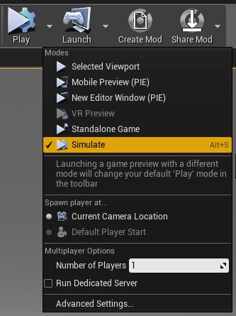
Then select the A_Fixture_Thumbnail_Generator from the World Outliner, and assign your newly created Rim(s) to the 'Rims to Generate' array


Fimally, click 'Generate Wheel Thumbnails' to generate the thumbnail files
You should now have a folder in your Rim folder called 'thumbnails'.
Open that folder, and the folder within, and save the newly created Thumbnail and CPP file:

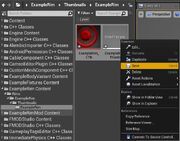
Your Rim Mod is now all set up!